Frequently Asked Questions with Answers 
DAQS
![]() What is the Difference between HF and LF DAQ, difference between
archive and transient mode?
What is the Difference between HF and LF DAQ, difference between
archive and transient mode?
![]() What is
the Structure of the programs and the files used?
What is
the Structure of the programs and the files used?
![]() How
to Start Low Frequency Acquisition?
How
to Start Low Frequency Acquisition?
![]() Which
Temperature sensor is used & what is the principle of calculation at cold?
Which
Temperature sensor is used & what is the principle of calculation at cold?
![]() What are
different IAP's tests & their purpose?
What are
different IAP's tests & their purpose?
![]() Are the
test name standard irrespective of the bench used?
Are the
test name standard irrespective of the bench used?
![]() Can we
by-pass the PLCSE?
Can we
by-pass the PLCSE?
MAGNETIC MEASUREMENT
![]() Why there is 630mm difference between Q-loc and MM shaft position?
Why there is 630mm difference between Q-loc and MM shaft position?
POWERING
![]() How to start Client Server (For power supply sharing)?
How to start Client Server (For power supply sharing)?
![]() How to
Start Power Supply?
How to
Start Power Supply?
![]() How to Manipulate the
Rotary Switch?
How to Manipulate the
Rotary Switch?
![]() Why MIITS
are measured at 20 ms?
Why MIITS
are measured at 20 ms?
![]() Why
minimum energy quenches are done with fast power abort disabled?
Why
minimum energy quenches are done with fast power abort disabled?
![]() When a
magnet is trained without any quench, how many provoked quench should be done
and why?
When a
magnet is trained without any quench, how many provoked quench should be done
and why?
![]() What is
SSL and why is it so called?
What is
SSL and why is it so called?
![]() Why do you
perform 2 successive SSL?
Why do you
perform 2 successive SSL?
DAQS
![]() What is the Difference between HF and LF DAQ, difference between
archive and transient mode? (Answered by G. Dangelo)
What is the Difference between HF and LF DAQ, difference between
archive and transient mode? (Answered by G. Dangelo)
![]() HF can acquire data
only in transient mode (waiting for a trigger). 152 channels are available.
Sampling of 50 kHz to 250 Hz for HF and 5kHz to 250 for MF.
HF can acquire data
only in transient mode (waiting for a trigger). 152 channels are available.
Sampling of 50 kHz to 250 Hz for HF and 5kHz to 250 for MF.
LF can acquire both in transient mode and archiver. Transient is waiting for a
trigger (1 kHz to 10 Hz, 3500pts/channel). Archiver mode is depending on a
variation of the signal E (max 1 Hz). 288 Channels available.
![]() What is the Structure of the programs and the files used? (Answered
by G. Dangelo)
What is the Structure of the programs and the files used? (Answered
by G. Dangelo)
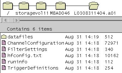
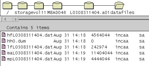
![]() In transient mode, HF
and LF data are based on circular buffer which acquire the data fro the ADC and
overwrite until it receives the trigger. Then it saves the data to the disk.
In transient mode, HF
and LF data are based on circular buffer which acquire the data fro the ADC and
overwrite until it receives the trigger. Then it saves the data to the disk.
In archiver mode, as the data is acquired it is immediately written to the disk.
Archiver mode:
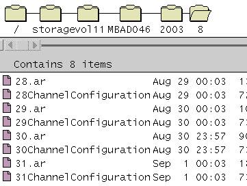
Transient mode:
![]() How To
Start Low Frequency Acquisition?
How To
Start Low Frequency Acquisition?
![]()
-
Open a new X-term window.
-
Type lf and press “Enter”. Then LabVIEW software will start and will start loading LF acquisition software. LF_ONLIN.VI window will appear. Subsiquently Strip chart Recorders4.vi window and Instrument Status And Control.vi window will appear.
-
On Instrument Status And Control.vi window click on “ON” button.
-
Then another window will appear and on that window click on “Load ” button.
-
Then another window will appear from that window select the configuration file and click “OK” button. (configuration files are listed in the following table)
-
Then it will go back to the earlier window. Now on this window click “RUN” button.
-
Now a new window will appear and software will download the configuration data to the LF acquisition microcomputer.
-
Once the down loading is over, “LF Acquisition armed” message will appear on the instrument status window of Instrument Status And Control.vi
-
To set the required file extension click on the “INFO” button, then a window will appear. From that window select the required file extension and click “Return” button. List of file extensions are given in a table below
-
For selecting the pen setting for LF viewer, click “Restore Penselection” button of Stripchart Recorders4.vi window. Now Penselection window will appear and from that select “Protect_view.sel” and click “OK” button.
-
To load another configuration file first stop the acquisition by clicking on “OFF” button on Instrument Status And Control.vi window and then click on “ON” button. Then follow the above steps 4 to 8.
|
LF Acquisition Configuration Files |
||
|
S. No |
Configuration File |
Purpose |
|
1 |
lf_aux_power_no_t_coil.txt |
For all measurement on corrector magnets. |
|
2 |
lf_maind_1_5ka_high_field_qh.txt |
For provoked quench at 1.5KA using high field quench heaters. |
|
3 |
lf_maind_1_5ka_low_field_qh.txt |
For provoked quench at 1.5KA using low field quench heaters. |
|
4 |
lf_maind_iap_high_field_qh.txt |
For Instrument Analysis Procedure with high field quench heaters. |
|
5 |
lf_maind_iap_low_field_qh.txt |
For Instrument Analysis Procedure with low field quench heaters. |
|
6 |
lf_maind_power_no_t_coil.txt |
For all magnetic measurements and quenches.. |
|
7 |
lf_maind_power_t_coil_1_5ma.txt |
For T-Coil data acquisition |
|
8 |
Lf_th_cyc_no_t_coil.txt |
For thermal cycle data acquisition |
|
9 |
lf_th_cyc_t_coil_1_5ma.txt |
For thermal cycle and T-Coil data acquisition |
|
LF HF Acquisition File Extensions |
|
|
File Extension |
Purpose |
|
a |
Training Quench at 1.8K, First run (before first thermal cycle). |
|
b |
Training Quench at 1.8K, Second run (before second thermal cycle). |
|
c |
Training Quench at 1.8K, Third run (before third thermal cycle). |
|
d |
High Ramp Rate Quench at 1.8K, Direct Ramp to Quench. |
|
e |
High Ramp Rate Quench at 1.8K, V-precycle Ramp to Quench. |
|
f |
High Ramp Rate Quench at 1.8K, Paused Ramp to Quench. |
|
g |
High Ramp Rate Quench at 1.8K, Other Quenches. |
|
h |
Provoked Quench - Quench Heater Delay. |
|
i |
Spare. |
|
J |
Spare. |
|
k |
Provoked Quench - Minimum Energy. |
|
l |
Spare. |
|
m |
Magnetic Measurements. |
|
n |
Training Quench at 4.3K. |
|
o |
Spare. |
|
p |
High Ramp Rate Quench at 4.3K. |
|
q |
Instrument Analysis Procedures. |
|
r |
Spare. |
|
s |
Spot Heater Provoked Quenches. |
|
t |
Test and Preparation. |
|
u |
Ultimate Field Reached (Manual Trigger). |
|
x |
Temporary Test and Preparation. |
![]() Which Temperature sensor is
used & what is the principle of calculation at cold? (Answered by G.
Dangelo)
Which Temperature sensor is
used & what is the principle of calculation at cold? (Answered by G.
Dangelo)
![]() The principle is the same at cold or warm. We
measure the resistance of the carbon sensor (which increase while cooling)
TT821. And
then we apply it’s calibration curve (coefficients) which has been measured in
a cryo lab.
The principle is the same at cold or warm. We
measure the resistance of the carbon sensor (which increase while cooling)
TT821. And
then we apply it’s calibration curve (coefficients) which has been measured in
a cryo lab.
![]() What are different IAP's tests
& their purpose? (Answered by G. Dangelo)
What are different IAP's tests
& their purpose? (Answered by G. Dangelo)
![]()
IAP @ warm High Field Q.H.
(Quench heaters – Voltage taps – Temperature gauge)
-
Check voltage tap integrity and continuity, as well as High Field quench heaters integrity at reception on the bench under powering.
-
Check integrity of temperature sensor and its fit.
IAP @ warm Low Field Q.H.
(Quench heaters – Voltage taps – Temperature gauge)
-
Check voltage tap integrity and continuity, as well as Low Field quench heaters integrity at reception on the bench under powering.
-
Check integrity of temperature sensor and its fit.
IAP @ cold
(Quench antenna compensation – Potaim card)
-
Check and improve if needed sensibility of quench antenna signals.
-
Check integrity of voltage taps and Potaim card adjustment
IAP @ warm Final.
(Voltage taps – Temperature gauge)
-
Check voltage tap integrity and continuity at the end of test, before dismantling from the bench.
-
Check integrity of temperature sensor and its fit at the end of test, before dismantling from the bench
![]() Are the test name standard irrespective of the bench used? (Answered
by G. Dangelo)
Are the test name standard irrespective of the bench used? (Answered
by G. Dangelo)
![]() Since all the cluster
will be identical, we can have the same tests and same name on all the clusters.
Improvement will be done.
Since all the cluster
will be identical, we can have the same tests and same name on all the clusters.
Improvement will be done.
![]() Can we by-pass the PLCSE? (Answered by G. Dangelo)
Can we by-pass the PLCSE? (Answered by G. Dangelo)
![]() Physically yes, but
PLCSE is made for safety reason and must not be by-passed.
Physically yes, but
PLCSE is made for safety reason and must not be by-passed.
MAGNETIC MEASUREMENT
![]() Why there is 630mm difference between Q-loc and MM shaft
position? (Answered by G. Dangelo)
Why there is 630mm difference between Q-loc and MM shaft
position? (Answered by G. Dangelo)
![]() 630 mm is half a
section length. In MM 12 sections cover the all the magnetic length. In Q-loc we
shift by ½ section to be more accurate on the ends of the magnet (where most of
the quench are located).
630 mm is half a
section length. In MM 12 sections cover the all the magnetic length. In Q-loc we
shift by ½ section to be more accurate on the ends of the magnet (where most of
the quench are located).
POWERING
![]() How to start
Client Server (For power supply sharing)?
How to start
Client Server (For power supply sharing)?
![]()
-
Open a new X-term window on SUN Workstation2, from command prompt type server and press “ENTER”. ( SUNMTA2> server )
-
Now server will start and server-running indication will be displayed.
-
From the command prompt type access and press “ENTER”. ( SUNMTA2> access )
-
Now access program will start and window, which gives the access to various power supplies, will appear.
-
From access program allocate the required Power supply to each test bench (to associated Sun workstation).
![]() How to start Power Supply?
How to start Power Supply?
![]() Check whether
the server program allocated the required power supply to the test bench (to
associated Sun workstation). If not, from access program allocate the required
power supply to the test bench and click “update” button. Then check whether
it is updated in the server program.
Check whether
the server program allocated the required power supply to the test bench (to
associated Sun workstation). If not, from access program allocate the required
power supply to the test bench and click “update” button. Then check whether
it is updated in the server program.
How to start Power Supply from MMP?
-
If MMP is not already started, from command prompt type MMP and press “ENTER”. ( SUNMTA2> MMP <ENTER> )
-
Now MMP program will start and a login window will appear. Type user names and pass word and click “Confirm” button.
-
Go to “HARDWARE” mode and load the hardware configuration file from “FILE” menu.
-
MBB_main_dipole.hmd For Main Dipole.
MBB_QCD.hmd For QCD.
MBB_correctors.hmd For Correctors. -
Then click “auto test” button to test all devise and communication. OR
-
Click on power supply icon, then a window will appear, from that window do auto test of power supply and communication.
-
Go to “REMOTE” mode and click on power supply icon. Then a window for controlling power supply will appear.
-
Click on the “Settings” button and check whether the upper limit of current, upper limit of ramp rate and default ramp rate are set properly.
-
Now it is ready to control Power Supply.
How to start Power Supply without MMP?
-
From command prompt type “power” and press “ENTER”. ( SUNMTA2> power <ENTER> )
-
Now a window for controlling power supply will appear.
-
Click on the “Settings” button and check whether the upper limit of current, upper limit of ramp rate and default ramp rate are set properly.
- Now it is ready to control Power Supply.
![]() Why MIITS are measured at 20 ms? (Answered by G. Dangelo)
Why MIITS are measured at 20 ms? (Answered by G. Dangelo)
![]() For a quench in inner
layer, studies have shown that the hottest spot (in outer layer) come at 20 ms
(due to heater delay at high current).
For a quench in inner
layer, studies have shown that the hottest spot (in outer layer) come at 20 ms
(due to heater delay at high current).
![]() Why
minimum energy quenches are done with fast power abort disabled? (Answered by G.
Dangelo)
Why
minimum energy quenches are done with fast power abort disabled? (Answered by G.
Dangelo)
![]() Minimum energy
quenches should be performed only with fast power abort disabled. This condition
is closer to the LHC machine quench condition.
Minimum energy
quenches should be performed only with fast power abort disabled. This condition
is closer to the LHC machine quench condition.
![]() When a
magnet is trained without any quench, how many provoked quench should be done
and why? (Answered by G. Dangelo)
When a
magnet is trained without any quench, how many provoked quench should be done
and why? (Answered by G. Dangelo)
![]() At the moment, the
baseline says 2 quenches
At the moment, the
baseline says 2 quenches
The 1st is to check integrity of the magnet protection (only at high current the
coil is under big pressure due to Lorentz forces)
The 2nd is to check that the 1st quench did not damage the magnet. Experience
has shown that one magnet became “sick” after the 1st quench only!
![]() What is
SSL and why is it so called? (Answered by G. Dangelo)
What is
SSL and why is it so called? (Answered by G. Dangelo)
![]() SSL is for Short
Sample Limit. It is a definition for particular type of test on a 1m long
superconducting cable placed into a magnetic field at a given temperature.
SSL is for Short
Sample Limit. It is a definition for particular type of test on a 1m long
superconducting cable placed into a magnetic field at a given temperature.
In our case we are at the limit of the cable by increasing the temperature (4.4
K).
![]() Why do
you perform 2 successive SSL? (Answered by G. Dangelo)
Why do
you perform 2 successive SSL? (Answered by G. Dangelo)
![]() To ensure
reproducibility at a given temperature, ie we are really at SSL (limitation by
the cable and mechanic).
To ensure
reproducibility at a given temperature, ie we are really at SSL (limitation by
the cable and mechanic).